

Key Factors to Consider When Selecting a Vertical Machining Center
Selecting a vertical machining center involves more than checking whether the finished part fits within the listed X, Y and Z-axis travel. The fixture occupies part of the working area. Tool length affects the available Z-axis clearance. Material and cutting conditions influence the required spindle speed, torque and guideway design. The number of operations also determines how much tool capacity is practical.
Before recommending a VMC, we normally review the part drawing, material, workpiece size and expected production volume. These details provide a better basis for machine selection than travel specifications alone.
Workpiece and Fixture Size
The finished-part dimensions are only the starting point when checking machine capacity. A vise, fixture, clamps and locating components all require space on the table. The cutting tool also needs enough clearance to approach the workpiece without interfering with the fixture, spindle or machine enclosure. For this reason, a part that appears to fit within the listed axis travel may still require a larger machine.
The following dimensions should be reviewed together:
• Raw material size
• Finished-part size
• Fixture dimensions
• Workpiece height above the table
• Tool length
• Required approach and clearance
• Workpiece and fixture weight
Table size and load capacity are also important, particularly for larger mould components, castings and heavy fixtures.
Spindle Speed and Torque
The suitable spindle specification depends on the material, cutting tool and machining process. Higher spindle speeds are commonly used with smaller tools, aluminium parts and finishing operations. Larger tools, deeper cuts and heavier steel machining may place greater emphasis on spindle torque. Choosing the highest available spindle speed does not automatically improve production. If most of the work uses larger cutters at lower speeds, torque characteristics may be more relevant than maximum rpm.
The spindle taper also affects the available tooling and cutting capability. BT40 is widely used for general machining and provides a practical balance between tool size, speed and flexibility. Larger spindle tapers may be considered for heavier cutting or larger tools. The complete process should be reviewed before deciding on spindle speed, motor output and taper size.
Tool Magazine Capacity
A VMC uses an automatic tool changer to complete several operations within one program. A simple component may require only a face mill, end mill, drill and tap. A mould, manifold or complex housing can require many more tools, including roughing, finishing and inspection tools.
If the tool magazine cannot hold the complete tool list, the operator may need to replace tools during production. This adds handling time and creates another point that must be managed. A larger magazine offers more flexibility, but it also adds cost and may not be necessary for straightforward parts. The required capacity should be based on the actual machining process and expected range of work.
Linear Guideways or Box Ways
Guideway design affects axis movement, cutting behaviour and the type of work for which a VMC is best suited. Linear guideways use rolling elements between the moving components. Their low-friction movement supports faster rapid traverse and responsive positioning. They are commonly selected for general machining, frequent tool movement and applications where cycle efficiency is important.
Box ways use sliding contact surfaces and are generally valued for rigidity and vibration damping. They are often considered for heavier cutting, larger tools and applications involving substantial material removal. These are general characteristics rather than fixed rules. A linear-guideway machine can still machine steel, and a box-way machine can still produce accurate finished surfaces. Machine structure, spindle design, tooling and cutting conditions all affect the final result.
SELICA provides both configurations for different production requirements:
• The SHV series uses linear guideways and is suitable for general machining, faster axis movement and applications requiring frequent positioning.
• The SMV series uses box ways and is intended for customers who place greater emphasis on rigidity, vibration damping and heavier cutting.
The selection should be based on the customer’s typical work rather than one occasional part.
SHV-1020 Machining Demonstration
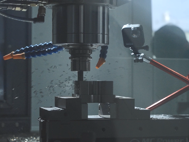
The SELICA SHV-1020 is a linear-guideway vertical machining center with X/Y/Z travel of 1020/550/580 mm. It uses a BT40 spindle and can be configured with a spindle speed of up to 15,000 rpm. The following video shows the SHV-1020 under actual machining conditions and provides a closer look at its working area and cutting movement.
Watch the SHV-1020 machining video:
https://www.facebook.com/share/v/16ob5Trfbx/
Special thanks to LIVE TOOLS Australia and REGAL MACHINERY Australia for their support in producing this video.
When to Consider a Fourth Axis
A standard VMC operates along the X, Y and Z axes. If the part requires machining on several sides or includes features around its circumference, a rotary table can be added as a fourth axis. This may reduce repeated clamping and help maintain the positional relationship between features. However, the rotary table, fixture and workpiece also occupy space and may reduce the usable machine travel. The decision should be based on the part geometry, setup method and production volume.
For a more detailed explanation, please see our article, When Does a Machining Center Need a Rotary Table?